Pусский

A rotary joint is a special mechanical seal that connects a static pipe to a rotating element, enabling liquid to be delivered from the static pipe to the rotating device for cooling, heating or pressurization. Also, a large variety of single and multi-channel unbalanced and balanced units are available to handle aqueous coolants, hydraulic oils, heat transfer oils, air, gas or steam.
Two rotary joint structures as mechanical seals are introduced below. Figure A shows the structure of a single fluid rotary joint. The pipe joint 1 is connected to the rotating cavity as the rotating part, and the joint body 6 is connected to the static cavity as the static part. The sealing part is composed of 7(spring), 8(flat pad), 9(sealing ring), 10(flat pad), 11(rubber sleeve). This structure has only one fluid channel (the rest parts are as follows:2 is the inner jump ring, 3 is the bearing, 4 is the sleeve, 5 is the outer jump ring). Figure B is a double fluid rotary joint structure, the pipe joint 1 is the rotating part connected with the rotary cavity, the joint body 11 and the pipe joint 9 are the static parts, which can be respectively connected to the two fluid static cavities, and there are fluids inside and outside the inner pipe, serial number 6 (spring), 10 (coupling sleeve), 1 (pipe joint), 13 (friction ring), 14 (rotary face) are sealing parts to prevent fluid leakage; between 8 (inner taper sleeve) and 16 (inner pipe) Seal to prevent fluid from mixing (2 is a retaining ring, 3 is a bearing, 4 is a sleeve, 5 is a pin, 7 is a retaining ring, 12 is a static ring, and 15 is a retaining ring). This structure is expanded on the basis of Figure A.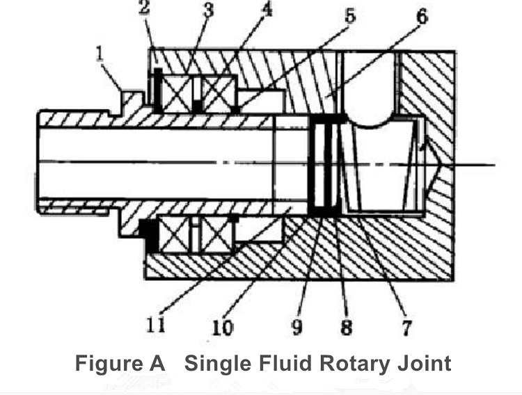
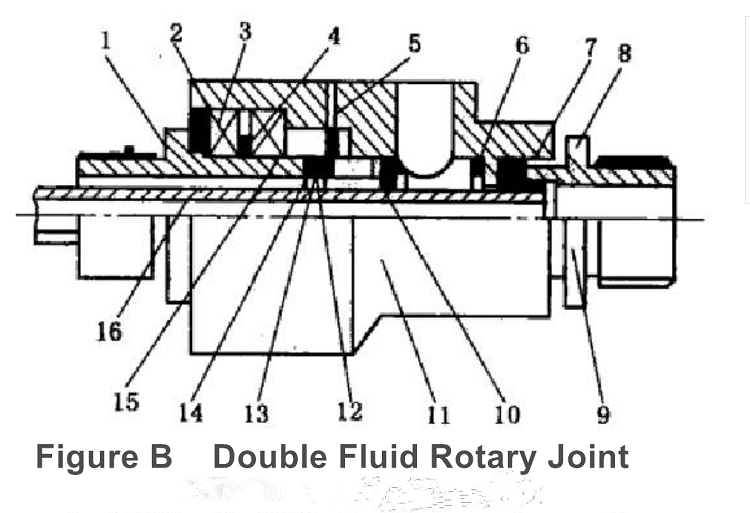
Two rotary joint structures as mechanical seals are introduced below. Figure A shows the structure of a single fluid rotary joint. The pipe joint 1 is connected to the rotating cavity as the rotating part, and the joint body 6 is connected to the static cavity as the static part. The sealing part is composed of 7(spring), 8(flat pad), 9(sealing ring), 10(flat pad), 11(rubber sleeve). This structure has only one fluid channel (the rest parts are as follows:2 is the inner jump ring, 3 is the bearing, 4 is the sleeve, 5 is the outer jump ring). Figure B is a double fluid rotary joint structure, the pipe joint 1 is the rotating part connected with the rotary cavity, the joint body 11 and the pipe joint 9 are the static parts, which can be respectively connected to the two fluid static cavities, and there are fluids inside and outside the inner pipe, serial number 6 (spring), 10 (coupling sleeve), 1 (pipe joint), 13 (friction ring), 14 (rotary face) are sealing parts to prevent fluid leakage; between 8 (inner taper sleeve) and 16 (inner pipe) Seal to prevent fluid from mixing (2 is a retaining ring, 3 is a bearing, 4 is a sleeve, 5 is a pin, 7 is a retaining ring, 12 is a static ring, and 15 is a retaining ring). This structure is expanded on the basis of Figure A.
From the above two rotary joint structures as mechanical seals, it can be seen that the rotary joint has different structures in different applications, but no matter how the structure changes, it includes three parts, namely the rotating part, the sealing part and the static part. The rotating part is connected with the rotating cavity, and the static part is connected with the static cavity. There is a complete fluid passage between the two parts, and the sealing part seals the fluid to prevent fluid leakage and fluid mixing.
When designing a rotary joint as a mechanical seal, the design forms are classified according to pressure, temperature, speed and fluid types. For details, please refer to the corresponding standard JB/T 8725-1998 for two typical designs.
When designing a rotary joint as a mechanical seal, the design forms are classified according to pressure, temperature, speed and fluid types. For details, please refer to the corresponding standard JB/T 8725-1998 for two typical designs.